Aller au contenu principal

What Is a PSC Steering Column and How Does It Work?

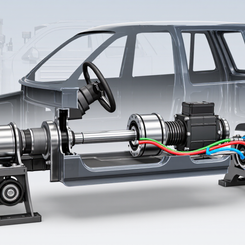
A PSC steering column is more than a metal shaft between the driver and the steering gear. It is a carefully aligned assembly that transfers steering input, supports the wheel, and helps manage vehicle control. In many off-road and performance vehicles, PSC refers to a steering-column system designed to work with hydraulic power steering equipment. Its exact layout can vary by vehicle, mounting position, and steering-box design.

Tom Lee, founder of PSC Motorsports, has expressed the practical goal this way: “Steering should feel predictable before it feels powerful.” That idea matters. A strong hydraulic pump cannot correct poor column alignment, loose joints, or incorrect shaft length. The column must rotate smoothly while maintaining secure connections through universal joints, splined shafts, bearings, and mounting brackets. Small details matter.

Inside the system, the driver turns the steering wheel. The column transfers that movement through the intermediate shaft. The steering box then converts rotation into linkage movement, while hydraulic assistance reduces the effort required. In a properly installed PSC steering column, the wheel should feel controlled, not vague or excessively light. A slight mistake can create vibration, binding, or delayed response.

The explanation is not completely simple. Vehicle weight, tire size, suspension geometry, and hydraulic pressure all influence steering behavior. Some installations also require custom brackets or shaft trimming. That is where careful measurement becomes essential. This guide examines the column’s construction, working process, installation considerations, and common symptoms of failure, while acknowledging one uncomfortable truth: even expert installations may need refinement after real road or trail testing.

What Is a PSC Steering Column and How Does It Work?

PSC Steering Column: Definition, Function, and SAE Terminology

A PSC steering column usually means a power-steering column assembly in supplier and workshop terminology. However, PSC is not a universal SAE component code. The assembly links the steering wheel to the steering gear through a shaft, bearings, joints, and a collapsible section. In column-assisted electric steering, the motor and reduction mechanism also sit near the driver’s knees. The column converts handwheel torque into steering input while preserving alignment and controlled movement.

SAE J1100 provides vehicle dimension terminology, while SAE J670 defines steering-related dynamic terms, including steering angle and steering torque. These references help engineers describe performance consistently. Safety requirements come from regulations such as FMVSS 203 and FMVSS 204, which address occupant protection and steering-control movement.

The NHTSA Traffic Safety Facts 2022 report recorded 42,514 U.S. traffic fatalities. That figure does not identify steering-column failures, but it shows why verified restraint and steering performance matter.

A loose intermediate joint may create a faint knock, delayed response, or uneven return after a turn. Small symptoms matter.

PSC descriptions can still be confusing.

Some documents use the term for the whole column; others mean only the assist module. I would not approve a replacement from the abbreviation alone. Check the torque path, collapsible length, mounting points, electrical signals, and diagnostic data. SAE terminology improves communication, but real service decisions require drawings, measurements, and tested specifications.

Core Architecture: Shaft, Bearings, Jacket, Couplings, and Assist Motor

What Is a PSC Steering Column and How Does It Work?

A PSC steering column connects the steering wheel to the steering gear. Its central shaft carries driver input through the column. Bearings support this shaft and keep rotation smooth. They also control side movement during steering. In a well-built assembly, the shaft should turn without grinding, binding, or noticeable play. Small clearances matter more than they appear.

The outer jacket surrounds and protects the moving parts. It also supports mounting points beneath the dashboard. Adjustable jackets can change the wheel position for driver comfort. Couplings join the column shaft to the steering gear input. These joints accommodate angle changes and reduce vibration transfer. A worn coupling may produce a dull knock or uneven steering feel.

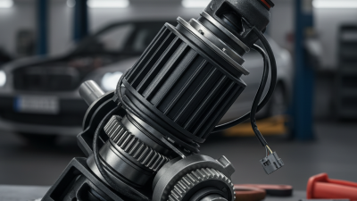
The assist motor supplies extra torque when steering effort rises. Sensors detect shaft movement and steering demand. A control unit then regulates motor output through the assist mechanism. This process should feel quiet and progressive, especially during parking maneuvers. Some designs place the motor near the column, while others use a different layout. Inspection experience shows that noise does not always indicate motor failure. Bearings, couplings, wiring, or mounting bolts may be responsible. That distinction is easy to miss. Technicians should check shaft play, connector security, fastener torque, and fault records before replacing parts. The architecture is straightforward, but diagnosis still requires patience.

Torque Path Explained: From Driver Input to Road-Wheel Steering

A PSC steering column, or power steering column, carries driver torque while adding controlled electrical assistance. The torque path begins at the steering wheel rim. Your hands create input torque, which passes through the column shaft and a torsion bar. A torque sensor measures the bar’s tiny twist. That twist signals driver effort and steering direction.

The control unit then commands an electric motor. The motor adds assist through reduction gearing, often a worm gear or belt drive. Mechanical torque still travels through the shaft. The combined torque reaches the steering gear, then the rack, tie rods, steering knuckles, and road wheels. The wheels respond with a smaller angle than the steering wheel, creating mechanical advantage and smoother control. The path is not perfectly linear. Friction, compliance, tire scrub, and temperature slightly change the driver’s actual feedback. That detail matters during calibration.

The International Energy Agency reported nearly 14 million electric cars sold globally in 2023, representing about 18% of new-car sales. Electrification increases demand for efficient, software-controlled steering assistance. Grand View Research estimated the automotive steering system market at roughly USD 35 billion in 2023. These figures help explain PSC development, but market growth alone does not prove better steering feel. A well-designed system must react quickly without masking road texture. Too much assistance feels vague. Too little feels heavy. Engineers still debate the ideal balance.

What Is a PSC Steering Column and How Does It Work? - Torque Path Explained: From Driver Input to Road-Wheel Steering

Typical engineering reference values for a passenger-vehicle power-assisted steering column and rack system. Actual specifications vary with vehicle size, steering geometry, tire characteristics, and assist calibration.

Torque-Path Stage Main Component Typical Data or Dimension How It Works Engineering Note
1. Driver Input Steering wheel and handrim 350–380 mm typical outside diameter The driver applies a steering force at the rim, creating an input torque around the steering-wheel axis. A larger wheel increases leverage but requires more hand movement for the same steering angle.
2. Steering Column Upper and lower steering shafts Common shaft diameter range: approximately 16–30 mm, depending on design and load requirements The column transmits rotational torque from the steering wheel toward the steering gear through one or more shafts. The column normally includes universal joints, collapsible sections, bearings, and protective covers.
3. PSC Assist Unit Power-steering assist motor and reduction gear Typical assist-motor output torque: approximately 2–8 N·m at the assist interface The PSC system adds torque in the commanded direction to reduce the effort required from the driver. Assist output is continuously regulated according to steering torque, vehicle speed, steering angle, and system status.
4. Torque Measurement Torsion bar and torque sensor Typical steering-column torsion-bar twist: approximately 1–5 degrees under normal driver input A small elastic twist represents the difference between driver-applied torque and the resistance from the road wheels. The sensor converts this twist into an electrical signal used to determine assist direction and magnitude.
5. Electronic Control Steering control unit Control-loop response is commonly measured in milliseconds; operating voltage is typically a vehicle low-voltage electrical system The controller interprets torque, steering-angle, motor-position, vehicle-speed, and diagnostic inputs before commanding the assist actuator. The controller reduces or disables assist when a fault, overheating condition, or implausible sensor signal is detected.
6. Column-to-Gear Connection Intermediate shaft and universal joints Typical joint operating angle: approximately 15–35 degrees per joint in many layouts Universal joints transfer rotation while allowing the steering column and steering gear to be positioned at different angles. Joint phasing, stiffness, and backlash affect steering smoothness, precision, and noise.
7. Steering Gear Pinion and rack Typical rack travel: approximately 120–170 mm; common steering ratio range: about 12:1–20:1 The pinion converts rotary motion into linear rack movement, which moves the steering linkage left or right. A lower numerical ratio gives quicker response; a higher numerical ratio generally requires more steering-wheel rotation.
8. Steering Linkage Inner and outer tie rods Typical tie-rod effective length: approximately 150–300 mm, depending on suspension layout Tie rods transmit rack movement to the steering arms while accommodating suspension movement and alignment changes. Tie-rod joints must allow angular movement without excessive play, which could reduce steering accuracy.
9. Steering Knuckle Steering arm and knuckle assembly Typical steering-arm effective lever: approximately 80–160 mm The steering arm converts tie-rod movement into rotation of the steering knuckle around the steering axis. Steering-axis inclination, caster, scrub radius, and Ackermann geometry influence steering effort and self-centering.
10. Road-Wheel Response Front wheel and tire contact patch Typical passenger-vehicle front-wheel steering angle: approximately 30–40 degrees at the inside wheel during a tight turn The knuckle turns the road wheel, changing the tire contact-patch direction and producing the vehicle's lateral response. The inside wheel normally turns farther than the outside wheel to follow the Ackermann steering geometry.
11. Driver Feedback Tire forces and steering return torque Typical on-center steering effort is calibrated for low friction and stable directional control rather than a fixed universal value Road forces travel back through the tire, knuckle, tie rod, rack, pinion, column, and torque sensor to provide feedback to the driver. Caster and tire self-aligning torque help the steering return toward center after a turn.
12. Safety and Fail-Safe Function Collapsible column, mechanical connection, and diagnostics Steering systems are designed to retain a mechanical steering path even if power assistance is unavailable If the assist system loses electrical power, the driver can normally continue steering manually, although steering effort increases substantially. The collapsible column is intended to manage column movement during a severe frontal impact while maintaining required steering integrity.

Note: The values shown are representative engineering ranges, not a specification for a particular vehicle. Steering effort, assist torque, rack travel, and steering ratio must be validated against the complete vehicle system.

Crash Safety Design: FMVSS 203 and the 127 mm FMVSS 204 Limit

What Is a PSC Steering Column and How Does It Work?

A PSC steering column transfers the driver’s steering input to the steering gear. It may include a shaft, joints, housing, bearings, and collapsible sections. During normal driving, these parts should feel rigid and precise. During a severe frontal crash, the column must manage energy instead of moving sharply toward the driver.

Crash Safety Design: FMVSS 203 and the 127 mm FMVSS 204 Limit

FMVSS 203 addresses driver protection from the steering control system during an impact. Its testing examines forces and contact hazards around the steering wheel and column. A compliant design uses controlled deformation, suitable padding, and secure mounting points. Small details matter, including joint alignment and fastener condition.

FMVSS 204 limits rearward displacement of the steering control to 127 mm, or five inches, during the specified crash test. This measurement helps control intrusion into the driver’s space. The limit does not mean every damaged column will move exactly 127 mm. Real crash angles, restraint use, and vehicle structure can change the result. They complicate inspection.

A bent shaft, broken bracket, or displaced mounting plate can indicate serious damage. Visual checks alone may miss internal deformation. Technicians should compare measurements with the applicable regulatory procedure and vehicle repair data. A replacement part may fit physically yet behave differently under impact. That uncomfortable possibility deserves attention.

Electronic Control and Diagnostics: ISO 26262 ASIL Requirements for PSC Systems

A PSC steering column combines mechanical steering with an electric assist motor, sensors, and an electronic control unit. Unlike hydraulic systems, it can adjust assistance through software and operating conditions. The ECU interprets steering torque, column position, vehicle speed, and motor current. That convenience creates safety responsibilities. A software fault can change steering assistance within milliseconds.

Under ISO 26262, engineers begin with an item definition and hazard analysis. ASIL is assigned according to potential harm, exposure, and controllability. The required level may range from QM to ASIL D. It depends on the vehicle function, not simply the steering column itself. A steering assistance loss may require stricter controls than a minor diagnostic warning.

Diagnostics begin with sensor plausibility checks and independent monitoring. Torque sensors often use redundant channels with separate signal paths. The ECU also supervises watchdog timing, memory integrity, voltage, temperature, and motor current. When readings disagree, the system should detect the fault and enter a defined safe state. That state might reduce assistance, maintain limited control, or alert the driver.

Short faults need rapid handling. Longer failures require controlled degradation. Verification includes fault injection, hardware-in-the-loop testing, and environmental stress tests. Engineers measure detection time, diagnostic coverage, and unintended torque. Traceable evidence matters.

One practical weakness is intermittent wiring failure. It may pass laboratory tests but appear after vibration, moisture, and temperature cycling. Real roads remain less predictable. A missed fault can expose gaps in assumptions, especially when software, hardware, and mechanical tolerances interact. Safety reviews should challenge those assumptions repeatedly.

ISO 26262 Hardware Architectural Metric Targets for PSC Steering Systems

The chart shows the ISO 26262 hardware architectural metric targets commonly used when evaluating safety-related electronic control and diagnostic functions in PSC steering systems. SPFM measures resistance to single-point and residual faults, while LFM measures resistance to latent faults. ASIL A has no specified minimum target for these metrics in ISO 26262.